Hardware room P-236TK
Basic equipment:
Equipment T-230-06 - 4 parts.
Block BGO-M - 1 room.
Block BAK-40F1 - 1 k.
Remote control PT-M - 4 k.
Shield PASH-M1 - 4 k.
The hardware provides:
Direct service TF connection
Total weight– 13500 kg
Crew = up to 14 people
Hardware room P-245-K
Basic equipment:
UKCH device
Telegraph channel switching unit (BTG-40M)
Block of reserve telegraph channels (BRTG-20U)
Control device for direct printing connections (KU-BP)
Telegraph concentrator (KTG-10J)
Telegraph operator's console (PT-M)
Group equipment block (BGO-M)
Channel state data transmission unit (CPDSK)
Scoreboard (TO-64)
Device ETI-69
Telegraph apparatus (LTA-8)
Telegraph apparatus (RTA-7M)
The hardware provides:
All hardware equipment
Hardware room P-245-KM is a cross of telegraph channels and is intended for:
COMPOSITION OF HARDWARE EQUIPMENT
A) Main equipment:
UKTCH device - 2 k.
Voice-frequency telegraphy equipment:
P-327-2 - 8 k.
P-327-3 - 4 k.
P-327-12 - 5 k.
Adapter device P-327-PU6 - 2 k.
Telephone intercom P-327-TPU-3 k.
Remote control panel-TG - 2 k.
Transition device block (BPU) - 1 unit.
Stativ (SKK) - 1 k.
Channel state data receiving unit (BPDSK) - 1 unit.
Electronic switch (KA-36) - 1 k.
System SUS-3M - 1 k.
Specialized electrical device (P-115A) - 1 k.
Unified video control device (1VK-40) - 1 part.
Hardware room P-232-1K
UVK block АВС-0102 - 1 unit.
UVK block АВС-1306 - 1 unit.
UVK block АВС-1313 - 1 unit.
The hardware provides:
21) Hardware P-328TK-1
The hardware provides:
switching on each set of T-230-3M1 and T-208
any telegraph channel introduced or created by P-327;
Simultaneous classification of up to 4 telegraph channels
Simultaneous pairing with 2 ZAS
Reliability and imitability of telegraph information
Inclusion of 2 reserve channels for calling devices;
Conducting telegraphic exchange through start-stop outputs
Switching to any equipment T-206, T-260-06 of any introduced pulse channel;
Receiving and sending call signals on the 2nd res. TG channels;
Operation of the service TGA in one of the modes.
Formation in each of the 2 introduced KFC 2 or 3 TG channels using P-327-2 and P-327-3 and switching of these TG channels to T-206-Zm1 and T-208 with its own equipment or issuing 2 TG channels to other TG hardware rooms;
Direct TF and GGS
Direct SS TF
SS TF with hardware US and PU subscribers
Duplex GGS between the body and the equipment cabin
Transport base:- KAMAZ – 4310 (body KB 1.4320D).
R consumption basic equipment = 2.8 kVA
R consumption total = 8.2 kVA
Total weight – 15100 kg
Crew = 7 people
Dimensions 8000mm x 2550mm x 3542mm
Hardware room P-328-TK is designed to provide classified telegraph communication via telegraph (low-speed) and pulse (medium-speed) channels of the US control points of OK and BC.
COMPOSITION OF HARDWARE EQUIPMENT
Basic equipment:
Equipment T-2O6-ZM - 4 sets.
RCD-ZMT device - 1 set.
Linear switching unit (BLK-M1) - 1 set.
Telegraph switching unit (BCTS) - 2 sets.
Terminal equipment status sensor (DSOA) - 2 sets.
Linear output attachment (PLV-2) - 2 sets.
Block AB-481 - 2 sets.
Voice-frequency telegraphy equipment P-327-2 - 2 sets.
Telegraph apparatus (LTA-8) - 10 sets.
Device ETI-69 - 1 set.
Group association block (BGO-M) - 1 set.
Telegraph operator's console PT-M - 2 sets.
BASIC TACTICAL AND TECHNICAL DATA OF THE HARDWARE
The hardware provides:
1. Reception of 8 TG channels through crossover hardware rooms or directly from channel-forming hardware rooms and their switching
2. Reception of 4 TG channels from radio stations of receiving machines and their switching
3. Reception of 2 PM channels, their switching to P-327-2 equipment
4. Simultaneous operation in secret mode via 4 TG channels
7. Measurement of characteristics of TG channels
8. Conducting official telegraph conversations over TG channels using service TG devices.
9. Organization of direct GHS and telephone communication with interacting hardware devices.
10. Conducting official negotiations through internal telephone exchange.
12. Maintaining simplex radio communication on the spot and on the move with hardware control systems using the R-105M radio station.
Hardware room P-236TK- the control room with terminal telegraph devices is designed to receive start-stop outputs of the T-206-3M1 and T-230-06 security equipment to terminal telegraph devices, provide direct-printing exchange, organize transit connections and circular communications.
The hardware room is part of the telegraph center of the field communication center KP (ZKP) OK (VS). When providing classified communications, it is used in conjunction with hardware P-238TK, P-238TK-1, P-244TN, P-242TN.
COMPOSITION OF HARDWARE EQUIPMENT
Basic equipment:
Equipment T-230-06 - 4 parts.
Telegraph switch (TG-15/10M1) - 1 k.
Circular connections block (BTsS-10M) - 1 unit.
Block BGO-M - 1 room.
Block BAK-40F1 - 1 k.
Remote control PT-M - 4 k.
Telegraph apparatus (LTA-8) - 8 k.
Shield PASH-M1 - 4 k.
The hardware provides:
Organization of TG communication via pulsed channels (C1-I) using T-230-06;
Conducting TG exchange via connected TG 15/10M1 start-stop outputs. –
Direct service TF connection
Direct service GGS from 4 RMs from windows.
Duplex GGS from the body from the cab with UPA-2, simplex GGS r/communication via R-105M on the spot and on the move.
Power supply: - from 2 autonomous, galvanically unconnected 3F – 380 V, 220 V; R consumption total = 11.1 kVA
Transport base: URAL-43203 (body K 2.4320)
Total weight – 13500 kg
Crew = up to 14 people
Hardware room P-245-K is a cross of telegraph channels and is intended for:
management of the US telegraph center;
reception and switching of PM channels to voice-frequency telegraphy equipment, as well as reception and switching of the remaining PM channels to hardware TFCs;
formation and distribution of telegraph channels via communication hardware;
monitoring the quality of channels (automatically or manually using instruments);
formation of up to 10 telegraph connections.
Basic equipment:
UKTCH device - 1 k.
Voice-frequency telegraphy equipment:
P-327-2 - 8 k.
P-327-3 - 2 parts.
P-327-12 - 2 parts.
Telegraph channel switching unit (BTG-40M) - 2 k.
Block of backup telegraph channels (BRTG-20U) - 1 unit.
Control device for direct-printing connections (KU-BP) - 1 part.
Telegraph concentrator (KTG-10J) - 1 k.
Adapter device P-327-PU6 - 1 k.
Telegraph operator's console (PT-M) - 2 k.
Group equipment block (BGO-M) - 1 unit.
Channel state data transmission unit (BPDSK) - 1 unit.
Scoreboard (TO-64) - 1 part.
Device ETI-69 - 2 parts.
Telegraph apparatus (LTA-8) - 1 part.
Telegraph apparatus (RTA-7M) - 1 part.
The hardware provides:
Reception of 20 PM channels on the UKTCH and switching of 14 of them for secondary compaction to the P-327 equipment;
Switching of 8 telephone channels formed from the remnants of the CFC spectrum, compacted by P-327-2 equipment, into the telephone center equipment rooms
Creation of up to 46 telegraph channels using P-327 equipment and their transmission to BTG-40m units
Switching of 70 telegraph channels to connecting lines from telegraph equipment rooms
Measuring and quality control of telegraph channels
All hardware equipment mounted in a KB.4320 body mounted on the chassis of a URAL-43203 vehicle.
The power consumed by the hardware room at a network voltage of 380 V does not exceed 9.8 kVA.
The total weight of the equipment room is no more than 11340 kg.
The crew of the control room is 7 people.
Dimensions of the equipment room, mm: length - 8260, width - 2550, height - 3384
Hardware room P-245-KM is a cross of telegraph channels and is intended for:
Management of the US telegraph center;
Reception and switching of voice-frequency channels to voice-frequency telegraphy equipment;
Formation, reception and switching of telegraph channels to the hardware of the communication center;
Monitoring the quality of channels (automatically or manually using instruments);
Automated processing and documentation of information about the state of communications and voice-frequency telegraphy equipment and delivery of this information to the control center of the communication center.
COMPOSITION OF HARDWARE EQUIPMENT
The P-245-KM hardware kit includes:
A) Main equipment:
UKCH device
Voice-frequency telegraphy equipment:
Adapter device P-327-PU6
Telephone intercom P-327-TPU
Remote control panel-TG -
Transition device block (TUB).
Stativ (SKK) -
Channel state data receiving unit (BPDSK) -
Electronic switch (KA-36) -
System SUS-3M -
Specialized electrical device (P-115A)
Unified video control device (1VK-40)
Hardware room P-232-1K designed for receiving, processing, accounting and delivery of telegraph correspondence to the addressees of the control point, to individual receiving machines and hardware of the communication center.
Equipment for collecting, displaying and documenting information about the passage of telegraph messages:
UVK block АВС-0102 - 1 unit.
UVK block АВС-1306 - 1 unit.
UVK block АВС-1313 - 1 unit.
Asynchronous concentrator KA-36 - 1 k.
Table-character indicator RIN-609 - 3 parts.
Telegraph apparatus RTA-7m - 2 units.
Photo reader FS-1501 - 1 part.
Band puncher PL-150 - 1 kit.
Basic tactical and technical data The hardware provides:
1.Connecting up to 10 advanced terminal telegraph hardware rooms
3. Connecting the hardware P249k
4. Collection and synthesis of data on the passage of signals and telegraph messages and transfer of this information to the P-249k equipment room.
5. Reception from the P-249k hardware room of information about the state of telegraph communications.
6. Automatic counting of control periods for the passage of signals and telegraph messages.
11. Connecting subscriber lines from long-distance and internal telephone exchanges.
13. Service radio communications using 5 selective frequencies and one circular calling frequency.
9) cabling- this is the most important component of the process of deploying mobile and stationary control equipment
It includes:
1. Intra-node connection of elements, hardware, stations of the control system with each other;
2 . Equipment of subscriber networks at the control center;
3 . Equipment of lines for remote control of transmitters and transmission of channels from remote distribution zones;
4. Power supply network equipment for hardware rooms.
Components of PUS cabling: equipment of transmission lines of channels from remote distribution zones, connection of elements and hardware rooms to each other.
To solve these problems, transmission system equipment is used, as well as long-distance field communication cables, radio relay stations, light field cables and intra-node cables.
The equipment of the Topaz and Azur complexes is used as channel transmission systems, installed in the OPM, ADU, in node transmission complexes or in hardware seals.
The cable is laid on the surface of the earth:
cable layer;
using a bunker method from a vehicle platform or using trolleys;
manually using a trolley.
The order of laying intra-node trunk lines is determined by the head of the control center. The typical installation order would be:
between hardware of different elements:
a cable from other hardware devices is laid to the cross-over hardware rooms;
from the hardware TG ZAS to the receiving machines of the radio center;
from receiving machines and individual machines of the radio center to the hardware TF ZAS;
from hardware CKS (GKO) to hardware TF ZAS or TG ZAS and cross-connections of telegraph (P-245K) and TLF (P-246K) channels.
from hardware control of US elements to hardware control of US.
between hardware inside elements (centers):
at the receiving center - from receiving machines of radio stations and individual receiving machines to the radio control room;
at the transmitting radio center - from radio transmitters, radio stations to remote control hardware (radio transmitting nodes);
in channel formation groups located outside the control center - from radio relay, tropospheric stations - to channel transmission hardware;
at the call center - from the hardware TF ZAS to the TLF station ZAS, to the hardware cross of TLF channels, from the TLF station of long-distance and internal communications to the hardware cross of TLF channels;
at the TLG center - from the hardware TG ZAS to the hardware crossover of telegraph channels.
Subscriber communication networks, which are part of secondary networks, are a set of terminal subscriber devices installed at the workplaces of officials at the control point, subscriber lines and switching devices.
Currently, in accordance with the “Manual on Communications of the Armed Forces of the Republic of Belarus” and the secondary networks being deployed at the command posts of the Ground Forces formations, the following subscriber networks must be equipped:
TLF station for long-distance classified communications;
TLF station of open (unclassified) communication;
regime automatic TLF station (TLF intercom station);
center for automation equipment for command and control of troops (forces);
operational loudspeaking communication;
secret telegraph communications;
video TLF communication.
At stationary control centers, distribution (subscriber) networks are equipped with the help and means of stationary communication centers:
TLF secret communication station;
regime automatic TLF station;
comprehensive, including open networks of TLF long-distance communication stations, internal automatic telephone exchange, operational (dispatcher) TLF (loud-speaking) communication installations, intra-facility warning, clock registration.
The following factors determine the capacity, structure and branching of subscriber distribution networks:
the number and type of personal terminal devices installed at the workplaces of officials at the control point;
the degree of dispersion of control point elements on the ground;
introduction of devices for collective use, including telephone calls;
fulfillment of the requirements of governing documents for the creation of a unified subscriber network for classified communications;
capabilities of terminal hardware devices to remove terminal devices;
the degree of equipment of the headquarters vehicles of mobile launchers with communications equipment;
the staffing of the control center serving this control point with personnel and communications equipment.
As part of the subscriber network of the long-distance TLF station classified communication of a mobile control unit includes the following elements:
terminal telephone sets, installed at the workplaces of officials of the control point (negotiation points) of type P-171, AT-3031;
Subscriber lines deployed by ATGM cable, PRK cable with a capacity of 20x2, 10x2 and 5x2, light field cable P-274M:
telephone exchanges of types P-252M1, P-252M2, as well as switchboards P-209 (P-209I) in hardware rooms P-244TM (P-244TN);
cable equipment consisting of input panels, distribution and transition couplings.
The subscriber network of the TLF unclassified communication station includes:
telephone sets of the TAN-68, TAN-72 type;
Subscriber lines with field cables such as PRK, PTRG and P-274;
switching devices equipped in hardware rooms P-178-1 (P-178-II), P-225M.
A subscriber network of a secure automatic TLF station will be deployed at the association's control centers, designed for the exchange of secret information between department officials without the use of classification equipment.
Basic operational and technical capabilities
topological structures
technical equipment unmasking signs
organizational structures
Maintenance
maintainability
ergonomics and medical and technical requirements
energy intensity and consumption of consumables
The basic principles for constructing control systems as complex systems include the following:
Correspondence of their operational and technical capabilities to the needs of the control and communication system.
Structural organization.
Organizational and technical unity of control systems for various purposes.
Segregation of forces and means of communication centers.
Step by step development.
Combination of centralized and decentralized control
Telegraph devices played a big role in the development modern society. Slow and unreliable slowed down progress, and people looked for ways to speed it up. It has become possible to create devices that instantly transmit important data over long distances.
At the dawn of history
The telegraph in its various incarnations is the oldest of them. Even in ancient times, the need arose to transmit information over a distance. Thus, in Africa, tom-tom drums were used to transmit various messages, in Europe - a fire, and later - semaphore communication. The first semaphore telegraph was first called “tachygraph” - “cursive writer”, but then it was replaced by a more appropriate name “telegraph” - “long-distance writer”.
First device
With the discovery of the phenomenon of “electricity” and especially after the remarkable research of the Danish scientist Hans Christian Ørsted (the founder of the theory of electromagnetism) and the Italian scientist Alessandro Volta - the creator of the first and first battery (it was then called the “Volta pillar”) - many ideas for creating an electromagnetic telegraph appeared.
Attempts to manufacture electrical devices that transmit certain signals over a certain distance have been made since the end of the 18th century. In 1774, the simplest telegraph apparatus was built in Switzerland (Geneva) by the scientist and inventor Lesage. He connected two transceiver devices with 24 insulated wires. When an impulse was applied using an electric machine to one of the wires of the first device, the elderberry ball of the corresponding electroscope was deflected on the second. Then the technology was improved by the researcher Lomont (1787), who replaced 24 wires with one. However, this system can hardly be called a telegraph.
Telegraph devices continued to be improved. For example, the French physicist Andre Marie Ampere created a transmitting device consisting of 25 magnetic needles suspended from axes and 50 wires. True, the bulkiness of the device made such a device practically unusable.

Schilling apparatus
Russian (Soviet) textbooks indicate that the first telegraph apparatus, which differed from its predecessors in efficiency, simplicity and reliability, was designed in Russia by Pavel Lvovich Schilling in 1832. Naturally, some countries dispute this statement by “promoting” their equally talented scientists.
The works of P. L. Schilling (many of them, unfortunately, were never published) in the field of telegraphy contain many interesting projects for electrical telegraph devices. Baron Schilling's device was equipped with keys that switched the electric current in the wires connecting the transmitting and receiving devices.
The world's first telegram, consisting of 10 words, was transmitted on October 21, 1832 from a telegraph machine installed in the apartment of Pavel Lvovich Schilling. The inventor also developed a project for laying a cable to connect telegraph devices along the bottom of the Gulf of Finland between Peterhof and Kronstadt.
Telegraph apparatus diagram
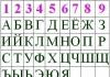
The receiving apparatus consisted of coils, each of which was included in connecting wires, and magnetic needles suspended above the coils on threads. On the same threads, one circle was attached, painted black on one side and black on the other. White color. When the transmitter key was pressed, the magnetic needle above the coil deflected and moved the circle to the appropriate position. Based on the combinations of circle locations, the telegraph operator at the reception determined the transmitted sign using a special alphabet (code).
At first eight wires were required for communication, then the number was reduced to two. To operate such a telegraph apparatus, P. L. Schilling developed a special code. All subsequent inventors in the field of telegraphy used the principles of transmission coding.
Other developments
Almost simultaneously, telegraph devices of a similar design, using induction of currents, were developed by the German scientists Weber and Gaus. Already in 1833, they established a telegraph line at the University of Göttingen (Lower Saxony) between the astronomical and magnetic observatories.
It is known for certain that Schilling’s apparatus served as a prototype for the telegraph of the Englishmen Cook and Winston. Cook became acquainted with the works of the Russian inventor in Heidelberg. Together with his colleague Winston, they improved the device and patented it. The device enjoyed great commercial success in Europe.
Steingeil made a small revolution in 1838. Not only did he lay the first telegraph line over a long distance (5 km), but he also accidentally made the discovery that only one wire can be used to transmit signals (the role of the second is performed by grounding).

However, all of the listed devices with dial indicators and magnetic needles had an incorrigible drawback - they could not be stabilized: during the rapid transmission of information, errors occurred and the text arrived distorted. The American artist and inventor Samuel Morse managed to complete the work on creating a simple and reliable telegraph communication circuit with two wires. He developed and implemented a telegraph code in which each letter of the alphabet was represented by certain combinations of dots and dashes.
The Morse telegraph apparatus is very simple. To close and interrupt the current, a key (manipulator) is used. It consists of a lever made of metal, the axis of which communicates with a linear wire. One end of the manipulator lever is pressed by a spring to a metal protrusion connected by a wire to the receiving device and to the ground (grounding is used). When the telegraph operator presses the other end of the lever, it touches another protrusion connected by a wire to the battery. At this moment, the current rushes along the line to a receiving device located in another location.
At the receiving station it is wound on a special drum narrow tape paper, continuously moving Under the influence of the incoming current, the electromagnet attracts an iron rod, which pierces the paper, thereby forming a sequence of characters.

Inventions of Academician Jacobi
The Russian scientist, academician B. S. Jacobi, in the period from 1839 to 1850, created several types of telegraph devices: writing, pointer, synchronous-in-phase action, and the world's first direct-printing telegraph device. The latest invention has become a new milestone in the development of communication systems. Agree, it is much more convenient to immediately read a sent telegram than to waste time deciphering it.
Jacobi's transmitting direct-printing apparatus consisted of a dial with an arrow and a contact drum. Letters and numbers were written on the outer circle of the dial. The receiving apparatus had a dial with an arrow, and in addition, advancing and printing electromagnets and a standard wheel. A typical wheel had all the letters and numbers engraved on it. When the transmitting device was launched from current pulses coming from the line, the printing electromagnet of the receiving apparatus was activated, pressed the paper tape to the standard wheel and imprinted the received sign on the paper.
Yuza apparatus
The American inventor David Edward Hughes established the method of synchronous operation in telegraphy, designing in 1855 a direct-printing telegraph apparatus with a standard wheel of continuous rotation. The transmitter of this device was a piano-type keyboard, with 28 white and black keys on which letters and numbers were printed.
In 1865, Hughes devices were installed to organize telegraph communication between St. Petersburg and Moscow, then spread throughout Russia. These devices were widely used until the 30s of the 20th century.

Baudot apparatus
The Yuz apparatus could not provide high speed telegraphy and efficient use of the communication line. Therefore, these devices were replaced by multiple telegraph devices, designed in 1874 by the French engineer Georges Emile Baudot.
The Baudot apparatus allows several telegrams to be simultaneously transmitted to several telegraph operators over one line in both directions. The device contains a distributor and several transmitting and receiving devices. The transmitter keyboard consists of five keys. To increase the efficiency of using the communication line, the Baudot apparatus uses a transmitter device in which the transmitted information is encoded manually by the telegraph operator.
Operating principle
The transmitting device (keyboard) of the apparatus of one station is automatically connected via a line to the corresponding receiving devices for short periods of time. The order of their connection and the accuracy of the timing of switching on are ensured by distributors. The pace of the telegraph operator’s work must coincide with the work of the distributors. The transmission and reception distributor brushes must rotate synchronously and in phase. Depending on the number of transmitting and receiving devices connected to the distributor, the productivity of the Baudot telegraph apparatus ranges from 2500-5000 words per hour.
The first Baudot devices were installed on the St. Petersburg - Moscow telegraph connection in 1904. Subsequently, these devices became widespread in the telegraph network of the USSR and were used until the 50s.

Start-stop device
The start-stop telegraph apparatus marked new stage development of telegraph technology. The device is small in size and easier to operate. It was the first to use a typewriter-type keyboard. These advantages led to the fact that by the end of the 50s, Baudot devices were completely ousted from telegraph points.
A. F. Shorin and L. I. Treml made a great contribution to the development of domestic start-stop devices, based on whose developments the domestic industry began to produce new telegraph systems in 1929. Since 1935, the production of devices of the ST-35 model began; in the 1960s, an automatic transmitter (transmitter) and an automatic receiver (reperforator) were developed for them.
Encoding
Since ST-35 devices were used for telegraph communication in parallel with Baudot devices, a special code No. 1 was developed for them, which differed from the generally accepted international code for start-stop devices (code No. 2).
After the Baudot devices were decommissioned, there was no longer a need to use a non-standard start-stop code in our country, and the entire operating ST-35 fleet was transferred to international code No. 2. The devices themselves, both modernized and new designs, were named ST-2M and STA-2M (with automation attachments).

Roll devices
Further developments in the USSR were aimed at creating a highly efficient roll telegraph machine. Its peculiarity is that the text is printed line by line on a wide sheet of paper, like a matrix printer. High productivity and the ability to transmit large volumes of information were important not so much for ordinary citizens as for business entities and government agencies.
- The T-63 roll telegraph apparatus is equipped with three registers: Latin, Russian and digital. Using punched tape, it can automatically receive and transmit data. Printing occurs on a roll of paper 210 mm wide.
- The automated roll electronic telegraph apparatus RTA-80 allows both manual dialing and automatic transmission and reception of correspondence.
- The RTM-51 and RTA-50-2 devices use 13 mm ink ribbon and roll paper of standard width (215 mm) to record messages. The device prints up to 430 characters per minute.
Modern times
Telegraph devices, photos of which can be found on the pages of publications and in museum exhibitions, played a significant role in accelerating progress. Despite the rapid development of telephone communications, these devices did not go into oblivion, but evolved into modern faxes and more advanced electronic telegraphs.
Officially, the last wire telegraph operating in the Indian state of Goa was closed on July 14, 2014. Despite the enormous demand (5,000 telegrams daily), the service was unprofitable. In the US, the last telegraph company, Western Union, ceased to perform direct functions in 2006, focusing on money transfers. Meanwhile, the era of telegraphs did not end, but moved into the electronic environment. The Central Telegraph of Russia, although it has significantly reduced its staff, still fulfills its duties, since not every village in a vast territory has the opportunity to install a telephone line and the Internet.
In the modern period, telegraph communication was carried out through frequency telegraphy channels, organized primarily through cable and radio relay communication lines. The main advantage of frequency telegraphy is that it allows you to organize from 17 to 44 telegraph channels in one standard telephone channel. In addition, frequency telegraphy makes it possible to communicate over almost any distance. A communication network made up of frequency telegraphy channels is easy to maintain and also has flexibility, which allows you to create bypass directions in the event of failure of linear means of the main direction. Frequency telegraphy turned out to be so convenient, economical and reliable that nowadays telegraph channels are used less and less.
Usage: in terminal devices of telecode communication, in particular in telegraph devices. The essence of the invention: to increase the depth of search for a defect in a telegraph apparatus and expand its functionality in a telegraph apparatus containing an input unit 7 (keyboard, transmitter) connected to the inputs of the transmitter 6, the transmitter output is connected to the input of the communication line, the input of the receiver is connected to the output of the communication line 2, and its outputs are connected to the inputs of display unit 1 (printer, display), additionally introduced are the first and second switches 4, 5, modulo two adder 9, RS trigger 10, address counter 11, read-only memory (ROM) 12 and indicator 13. 1 ill.
The invention relates to telegraphy, namely to telegraph devices. The RTA-80 telegraph apparatus is known, containing an input device (keyboard, transmitter) connected to the inputs of the transmitter, the output of the transmitter is connected to the input of the communication line, the input of the receiver is connected to the output of the communication line, and its outputs are connected to the inputs of the display device (printer, display) . The disadvantage of this device is that when testing “on oneself”, test influences are applied to the transmitter input using an input device. The closest to the invention is the RTA-7 telegraph apparatus, containing an input device (keyboard, transmitter) connected to the transmitter, the output of which is connected to the input of the communication line, the output of which is connected to the input of the receiver, and its outputs are connected to the inputs of the display device (printer , display). However, when testing “on oneself”, the tests generated by the input device make it possible to determine the malfunction of the telegraph apparatus as a whole. The drawing shows a block diagram of the proposed temperature apparatus. The telegraph apparatus contains a display unit 1, a receiver 2, forming the receiving part 3 of the telegraph apparatus, the first and second switches 4, 5, a transmitter 6 and an input unit 7, forming the transmitting part 8 of the telegraph apparatus, a modulo two adder 9, an RS trigger 10, address counter 11, read-only memory (ROM) 12, indicator 13. The telegraph apparatus operates as follows. In the main operating mode, which consists in transmitting and receiving telecode information, the contacts of the first and second switches 4, 5 are in the left position (see drawing). At this time, an installation signal is generated at the installation output of the transmitter 6, with which the RS trigger 10 and the address counter 11 are set to their initial state. In the self-diagnosis mode, switches 4 and 5 are set to the right position and the installation signal is removed from the R-input of RS-trigger 10 and address counter 11. At the information output of transmitter 6, serial code bits are formed, transmitted information into the communication line. The very first bit of the information pulse received from the output of transmitter 6 to the V-input of address counter 11 allows the arrival of clock pulses from the clock output of transmitter 6 to the C-input of address counter 11. Pulses from the outputs of address counter 11 arrive at the address inputs of ROM 12. Reference information pulses read from ROM 12 arrive at the first input of the adder 9 and through the closed elements of the first switch 4 to the information input of the receiver 2. The second input of the adder 19 receives information from the output of the transmitter 6. Thus, the reference information read from the ROM is compared 12, with information coming from the output of the transmitter 6. If there is a mismatch, a signal will appear at the output of the adder 9 that sets the RS trigger 10 to the “single” state. Indicator 13 will register the “DEFECT” signal. At the output of the display device 1, in the event of a malfunction of the receiving part of the telegraph apparatus, information will appear that uniquely corresponds to that supplied to the input of the input block 7. In the event of a malfunction of the receiving part 3 of the telegraph apparatus, the output information at its output differs from the input supplied at the input of the input block 7. Consequently, the consumer has the opportunity not only to determine the malfunction of the telegraph apparatus, but also to specifically indicate which part of the telegraph apparatus is faulty: transmitting or receiving. This increases the depth of defect search by 50%. In addition, in the event of a malfunction of the receiving or transmitting part (separately) of the telegraph apparatus, the consumer can only transmit or only receive information. This expands the functionality of a generally faulty telegraph apparatus by 50%.
Claim
A TELEGRAPH APPARATUS containing a series-connected input block and a transmitter, a series-connected receiver and a display block, characterized in that the first and second switches, a modulo two adder, an RS flip-flop, an address counter, a read-only memory (ROM) and an indicator are included, and the common contact of the first switch is connected to the information input of the receiver, the first contact is connected to the communication line output, and the second contact is to the first input of the modulo two adder and the ROM output, the first contact of the second switch is connected to the communication line input, the second contact is to the second input of the adder modulo two, and the common contact is to the output of the transmitter and the V-input of the address counter, the setting output of the transmitter is connected to the R-input of the RS flip-flop and the R-input of the address counter, the clock output of the transmitter is connected to the C-input of the address counter, the outputs of which are bitwise connected to the address inputs of the ROM, the output of the modulo two adder is connected to the S-input of the RS flip-flop, the output of which is connected to the input of the indicator.
Reference data on the content of precious metals in: RTA-80. Data is provided from open sources: product passports, forms, technical literature, technical reference books. Content of precious metals (Precious metals): gold, silver, platinum and platinum group metals (PGM - palladium, etc.) per 1 piece in grams. Gold: 1.94 Silver: 22.3 Platinum: 0 MPG: 0 Note:
RTA-80
Reference data on the content of precious metals in: RTA-80. Data is provided from open sources: product passports, forms, technical literature, technical reference books. Content of precious metals (Precious metals): gold, silver, platinum and platinum group metals (PGM - palladium, etc.) per 1 piece in grams. Gold: 3.967 Silver: 37.842 Platinum: 0 MPG: 0.042 Note: […]
RTA-7M
Reference data on the content of precious metals in: RTA-7M. Data is provided from open sources: product passports, forms, technical literature, technical reference books. Content of precious metals (Precious metals): gold, silver, platinum and platinum group metals (PGM - palladium, etc.) per 1 piece in grams. Gold: 5.5767 Silver: 25.998 Platinum: 0 MPG: 0 Note: […]
RTA-80
Reference data on the content of precious metals in: RTA-80. Data is provided from open sources: product passports, forms, technical literature, technical reference books. Content of precious metals (Precious metals): gold, silver, platinum and platinum group metals (PGM - palladium, etc.) per 1 piece in grams. Gold: 8.127 Silver: 19 Platinum: 0 MPG: 0 Note: […]
RTA-80-01
Reference data on the content of precious metals in: RTA-80-01. Data is provided from open sources: product passports, forms, technical literature, technical reference books. Content of precious metals (Precious metals): gold, silver, platinum and platinum group metals (PGM - palladium, etc.) per 1 piece in grams. Gold: 2.271 Silver: 25.022 Platinum: 0.007 MPG: 0.002 Note: […]
RTA8-5
Reference data on the content of precious metals in: RTA8-5. Data is provided from open sources: product passports, forms, technical literature, technical reference books. Content of precious metals (Precious metals): gold, silver, platinum and platinum group metals (PGM - palladium, etc.) per 1 piece in grams. Gold: 0 Silver: 22.43 Platinum: 0 MPG: 0 Note: […]
STA-M67
Reference data on the content of precious metals in: STA-M67. Data is provided from open sources: product passports, forms, technical literature, technical reference books. Content of precious metals (Precious metals): gold, silver, platinum and platinum group metals (PGM - palladium, etc.) per 1 piece in grams. Gold: 0 Silver: 0.86 Platinum: 0 MPG: 0 Note:
STA-M-67
Reference data on the content of precious metals in: STA-M-67. Data is provided from open sources: product passports, forms, technical literature, technical reference books. Content of precious metals (Precious metals): gold, silver, platinum and platinum group metals (PGM - palladium, etc.) per 1 piece in grams. Gold: 0 Silver: 0.538 Platinum: 0 MPG: 0 Note: […]
Basic performance characteristics and composition of hardware data exchange equipment (DAE)
Type: Hardware data exchange (AOD)
Purpose: To ensure communication, automatic reception of data, their distribution and classification (declassification), imitation protection, protection against errors in the exchange of data circulating in the ODS, implemented on the basis of the T-235 CTS, as well as for storage with objects equipped with the T-244 CTS -AOD is used as a PCCS of the core network of the PD US KP (ZKP) connection.
Composition of the main equipment:
Set T-235-4 (T-235-5),
- interface kit T-235-7,
- computer complex ABC-1102 (including ABC-0102, ABC-0201, ABC-0306),
- software package,
- cassette magnetic recording machine KAMZ-023-01,
- telegraph apparatus RTA-7,
- display TG-01,
- radio station R-171M-2 set,
- radio station R-134-1 set,
- radio station R-163-10V and equipment R-163-AR,
- switching device, service communication, power supply.
Possibilities:
AOD provides:
1.Connecting connecting lines from channel-forming hardware and hardware cross-connects for receiving communication channels and service communication circuits.
2. Simultaneous transmission of information via 17 communication channels.
3. When interacting with subscriber ODS:
- packet-by-packet reception of messages, temporary storage of packets, generation of receipts for receiving packets,
- ordering of packets, their stitching into messages, issuing receipts and batch-by-packet issuance of messages in communication channels,
- adjustment and updating of route and transport tables to the subscriber SOD TZU sets,
- generation and transmission of service commands to limit the flow of less categorical messages,
- control of the availability of key documentation.
4. When interacting with ASUS.
- input and adjustment of MAT,
- issuing results of monitoring the failure of messages, monitoring communication status automatically or on request, monitoring hardware hardware,
- exchange of service messages with ASUS hardware control rooms,
- issuance of official messages about the facts of illegal activity,
- issuing statistical (final) information about the passage of messages through the ANM to the automated control system.
5. Interface with objects equipped with KTST-244.
6. Packet exchange of messages up to 5000 characters long.
7. Priority transmission and processing of messages in accordance with four categories of urgency according to service discipline.
8. Input and adjustment of MAT from elements of the ODS control system.
9. Exchange of unicast, multicast and broadcast messages
10. Manual crossing of communication channels connected to the inputs of the hardware room to the channel inputs of the T-235-4(5) and T-235-1B equipment.
11. Service communication with the hardware of the communication center.
12. Power supply from a three-phase alternating current network with a voltage of 380 V and from an electrical power take-off unit from the transport base engine, from an ED-8-T400 electrical unit.
When working in a parking lot and on the move using radio equipment, the AOD ensures operation using two R-171M radio stations and one R-163-10B radio station.
One R-171M radio station ensures data exchange in the radio network of command post subscribers. The second radio station R-171M ensures data exchange with subordinate interacting and superior control units.
The R-163-10V radio station and R-163-AR equipment are used to link the equipment room to the radio access station and access the core network. To work with remote subscribers, the R-134 radio station is used.
Transport base- MT-LBU.